THEORY OF BOAT LIFTS
James Green's Lifts on the Grand Western Canal were based on a principal proposed by Doctor Anderson in about 1796.
They worked on a balance system whereby the descending caisson provided sufficient force to raise an identical ascending caisson. This was achieved by adding a small quantity of extra water to the upper caisson. The boats floated in water when in the caisson.
The caissons were operated full of water. Archimedes Principal determined that the system could cope with a full range of boat movements, the worst case being an empty boat descending with a fully laden boat ascending. Because each boat displaced its own weight of water the system was balanced providing the caissons were identical and the upper and lower pond water depths were the same. The addition of an extra two inches of water to the upper caisson provided sufficient force to overcome gravity and friction causing the caissons to start moving. Control was achieved by a brake acting through gears on the centre main wheel.

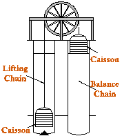
The figure on the left shows the arrangement of the caissons. They were connected by three heavy wrought iron lifting chains, which passed over 17ft diameter cast iron wheels. Balance chains were attached to the bottom of the caissons to compensate for the change of length of the lifting chain falls as the caissons were raised or lowered. The balance chains were able to coil or uncoil as the caissons moved up or down. Lock gates and caisson gates were lifted together and a "forcing" arrangement was used to seal the caisson frames to the lock frames when the gates were opened. The length of the lifting chain was set using adjusting screws to cause the ascending caisson to stop two inches below the upper pond lock sill. This admitted the extra water required for motion to take place.
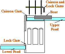
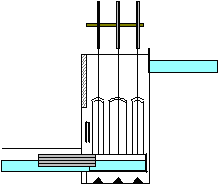
The following figures show only one of the lift chambers for clarity.


Vertically lifting lock gates were fitted to the upper and lower ponds and at each end of the caissons. At left a boat is entering the upper caisson, passing under the raised lock gates. When the boat is in the caisson both lock gates are closed, the brake released, and the caisson descends to the lower pond. At right the boat is shown leaving the caisson under the raised lock gates. Note how the balance chains are coiled at the bottom of the chamber.

In order for the descending caisson to line up with the lower pond lock gate the space below it had to be free of water. Water at canal level in this space would cause the lower caisson to float and prevent it mating with the lower lock gate. This would prevent the upper caisson reaching its correct height stopping the system from functioning correctly. Therefore a drain was required with an outlet below the canal bottom.
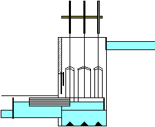
The first lift to be completed was at Taunton and problems arose because the water collecting in the bottom of the lift chamber could not be made to drain away satisfactorily, probably because the lower pond was only just above river level. The solution was to add a 4ft rise lock at the bottom of the lift giving an arrangement, possibly like that shown in the figure on the right which shows the modified lift. The boat is leaving the lower caisson and entering the lock that has been filled with water from above. Note the extra downstream lock gate. With the boat in the lock the upstream and caisson gates are closed and the lock drained into the lower pond. The downstream gate can then be opened and the boat passed through the lock.
Lifts offer several advantages to locks. They consume a lot less water and can achieve considerable changes of level in one go thus saving time. James Green calculated that his lifts would consume nearly 92% less water than an equivalent lock system and the time saved for a 46ft change of level would be 30 minutes. In practice things were not quite so rosie as Green made out but eventually the lifts were made to work and thereafter used successfully for 30 years. James Green was a daring and innovative engineer who designed and built structures that were at the forefront of the technology of the day. The 42ft lift at Greenham, the last to be completed, was built to the original design without a lock, and was reported to have worked correctly.
We have no drawings of the modified lifts and the diagrams are conjectural, based on written descriptions of their operation. Hopefully the excavations by SIAS at Nynehead will throw some light on how they were finally constructed.
